The elbow 2, the image of the slurry preparation tank after the transformation of i is divided into pipelines, the schematic diagram is as shown. After the transformation, the cleaning effect of the slurry preparation tank emptying pipeline was significantly improved, and the cleaning period was extended from two months before the transformation to more than six months. The number of people cleaning the pipeline was reduced from four people before the renovation to one person (only need to control the valve), saving a lot of manpower and maintenance costs. The cleaning time was shortened by nearly 2 hours, only lOmin. It not only saves materials, but also avoids the environment caused by the cleaning process. Pollution and personal injury in the magnificent area 111003 [Edit Li Wen] polyester plant slurry preparation tank emptying pipeline blockage analysis Liu Zhonghui Zhang Guoyue Yuyujing terephthalic acid PTA) and ethylene EG) is the main raw material for the production of polyester, EG / The PTA slurry molar ratio is 1.15. The PTA weighing device continuously measures the PTA powder and then adds it to the slurry preparation tank, and removes the foreign matter entrained in the powder through the vibrating screen to prevent damage to the weighing device. Under the action of the agitator, the slurry preparation is continuously carried out. The PTA and EG solutions form a uniform slurry suspension in the slurry preparation tank and generate a large amount of EG vapor. The device slurry preparation tank is provided with an emptying line for discharging. Produce EG vapor and balance tank pressure. The specification of the emptying pipeline is DN200, the flange of the pipeline cleaning section is 2.5m from the top of the tank, the distance between the two elbows is about 3m, the emptying pipeline is long and irregular, and the clogging material contains EG, the cleaning environment is wet and slippery, and the work is extremely inconvenient. And there are risks. Since the EG vapor entrained with PTA powder is discharged from the emptying pipeline, a large amount of PTA and EG viscous material is accumulated in the venting pipeline during the long-term production process, causing the clogging of the venting pipeline to cause the pressure in the tank to be too high, so that the PTA powder is countercurrent. It is emitted by the vibrating screen and cannot be supplied normally. A pipeline is taken out on the EG feed line; DN25) is connected to the outlet of the drain line, and a ball valve DN25 is added to control, and the purpose of periodically cleaning the blocked drain line is successfully achieved, and the slurry is prepared after the reformation. The tank has increased the dotted line frame UP5-22 twin-screw air compressor oil mixing reason analysis Li Maofang two-in-one Ingersoll Rand UP5-22 twin-screw air compressor, there is a defect that the oil is easy to mix water. After the oil flows out of the intake line during operation, the oil separator, the air filter, the oil filter, and the cooling oil (the compressor oil) are replaced, the same problem occurs again after about two months of operation. At that time, when the air compressor was set to start, the lower sewage valve of the gas-water separator was opened and closed after 5S delay. Therefore, it is suspected that the air-conditioner outlet check valve is not closed tightly and the air compressor is stopped, the water vapor on the air outlet pipe is reversed. Flow back to the oil and gas tank. Replace the air compressor outlet check valve, and change the lower sewage valve of the oil-water separator from the sewage discharge at startup to the sewage discharge at the time of shutdown, but there is still oil mixing after half a month of operation. However, the oil-mixed water phenomenon did not occur about one and a half years after the initial commissioning of the air compressor was completed, and the 2* air compressor that was put into operation at the same time did not show oil mixing. The air compressor adopts the centralized control mode, and uses the pressure switch on the gas storage tank to pass through the air compressor to jointly control the cabinet, and sends a start and stop signal to the air compressor. When the pressure of the gas storage tank drops to 0.68MPa, the main air compressor starts and stores. The pressure of the gas tank drops to 0.65MPa. The equipment air compressor is started when the equipment management and maintenance 2013 No.3 starts. When the pressure of the gas tank rises to 0.72MPa, the air compressor stops. After the air compressor starts the air supply, the main and spare air compressors are used. Rotation times. In order to achieve centralized control, the air compressor control wiring has been modified as appropriate, and the local and remote switching buttons have been added. The local control is controlled on the air compressor body. When the air compressor outlet pressure is lowered, it starts. When the pressure rises to normal, the intake valve is closed. After the air compressor outlet pressure reaches the set time, the air compressor is stopped. When the remote control is centralized control, the air compressor starts after receiving the start signal, and stops when the start signal is disconnected. After analyzing the two control modes, it can be found that the pressure in the centralized control mode does not close the intake valve and then delays the shutdown after the pressure rises to normal. This may be the cause of the air pressure oil mixing. A progressive analysis of the oil circulation system reveals that there is a temperature-controlled valve on the line. When the oil temperature is >70T, the temperature control valve opens and the compressor oil begins to cool through the oil cooler. Measure the temperature of the 1* and 2* air compressors. It is found that the temperature rises to 68T after the 1* air compressor starts, and the temperature rises to 72T after the 2* air compressor starts. Then observe the operation law of the two air compressors. When the air compressor is running, the outlet pressure is 0.08MPa higher than the tank pressure. When the tank pressure rises to 0.72MPa, the outlet pressure of the air compressor is about 0.8MPa. 2* After the air compressor starts, the cylinder pressure is close to the stop pressure, the air compressor When the pressure switch of the main body is operated and the outlet pressure of the air compressor falls back to the same level as the pressure of the gas tank, the gas is refilled, resulting in the 2* air compressor running time longer than the 1* air compressor, so the 2* air compressor operating temperature Above 1* air compressor. Because the screw air compressor selected by the power station has a large exhaust volume, the gas consumption of the unit during normal operation is small, and the air compressor starts the air supply for a short running time and a long interval, resulting in a low operating temperature of the air compressor. The condensed water generated by the air compression cannot be improved by the overhead conveyor system. He Wenbin Chongqing Hong Kong and Kowloon Co., Ltd. Integrated Terminal Uplift Belt Conveyor System (hereinafter referred to as the belt conveyor system) mainly includes the feeder section, 10m (5C1 section), 6-section conveying section such as 18m (5C2 section) and 20n (BC3 section), unloader section. Omron PLC controls the start, run and stop of the whole system and the corresponding protection stop. When the system is automatically controlled, the whole system starts with one button and stops with one button; manual control means separate control for each segment, and autonomous control starts and stops. In case of emergency, pull the rope switch next to the belt conveyor, the whole system will stop immediately, and the rope switch will be reset before it can start normally. The following improvements have been made to the problems with the belt conveyor system. Problem 1 When the belt conveyor system presses the stop button during operation, some sections cannot be stopped immediately. Press the stop button several times repeatedly, and occasionally stop. The main circuit inlet air switch must be disconnected to stop immediately, of which BC2 and BC3 The failure rate analysis and processing caused some parts of the whole system to be unable to stop during the operation: 1 PLC input part, start/stop button or hand automatic transfer switch failure, point signal can not be correctly fed back to PLC; 2PLC output part, output point Or output intermediate relay failure; 3 main circuit AC contactor failure; 4 corresponding paragraph line is caused by discharge, and the air compressor is just about one and a half years after it is put into operation, it coincides with the unit installation time, the gas consumption is large, the air compressor Frequent start-up, so the air compressor operating temperature is higher, so there will be no oil mixing phenomenon. 2 The air compressor has a slightly higher operating temperature of the air compressor due to the main body pressure switch action, so there is no oil mixing phenomenon. Firstly, adjust the pressure switch of the two air compressor main bodies. When it is guaranteed that the air pressure can be calibrated to the set value, let the body pressure switch act to extend the air compressor running time. At this time, measure the air compressor operating temperature. At 7 3T:. After a few days of operation of the air compressor, the oil mixing phenomenon improved significantly, indicating that the air compressor operating temperature has an important impact on the air compressor. In order to further solve the oil mixed water defect, the wiring of the air compressor is modified, and the air compressor will stop running after receiving the stop signal in the centralized control mode, and then close the intake valve and then delay the shutdown, and in the gas tank When the pressure too high signal arrives, the air compressor is stopped immediately, and the air compressor body pressure switch is returned to the original value. After measurement, the operating temperature of the two air compressors can be above 73QC, and no oil mixing occurs after operation. It can be seen that when the exhaust volume of the air compressor is selected, it should be considered according to the amount of gas used, and the air pressure opportunity with a large exhaust gas volume causes a short running time, thereby causing a low operating temperature. Low-pressure air compressors generally have their own control system. When using centralized control, keep the working process of the air compressor as much as possible. If the workflow is changed, it may have unintended consequences. W13.03-38 barrier. Checking one by one, the final reason for the failure is that the main circuit AC contactor that controls the start and stop of the belt motor of the belt conveyor cannot be normally and quickly disconnected after the coil is de-energized. The fault remains after replacing the new AC contactor of the same model. It was found that the power of the three-phase asynchronous motor of the BC2 section and the BC3 section was 15 kW. The CJX2-4011 AC contactor was used, and the fault disappeared after replacing the CJX2-5011 AC contactor with a large current rating. Since the power of the belt drive motor and the control AC contactor are not matched, the selection is too small. When the residual magnetism of the contactor is severe, the reaction elastic force of the contactor spring is smaller than the suction force of the residual magnet, and the main circuit of the control is energized and the main contact of the contactor is When the current is not disconnected, the passing current causes the magnetic field to be further strengthened, eventually causing the contactor contacts of the faulty section to not be normally disconnected. Switch group (at least 24 rope switches in each segment are connected in series) LX1LX7 action triggers LXK3 relay, which makes 11.07 in PLC program turn on, emergency stop output point W4.02 disconnects, system stops (). If any one of the rope ropes in the belt conveyor system malfunctions, the 1 input point of the PLC cannot accurately locate the conveying section where the rope switch is located, affecting the belt conveyor system operation analysis and processing to improve the belt conveyor system emergency power failure), to BC2 section Figure 丨Improve the emergency stop circuit of the front belt conveyor system (partial > *I cabinet 2 improved belt conveyor system emergency stop circuit (part)), if one of the rope switches is malfunctioning, LX2 action, relay LK2 coil In the PLC program, 17.01 is closed, the output points W7.00 and W402 are successively operated, and the system stops. This way, by detecting the state of the 17.0017.05 input point, the conveying section of the malfunctioning rope switch can be quickly confirmed, and then the corresponding paragraph belt conveyor is checked. The pull rope switch can eliminate the fault, save time and effort. W13.03-39 [Edit Ling Rui] equipment management and maintenance 2013No3 Rigid PCB
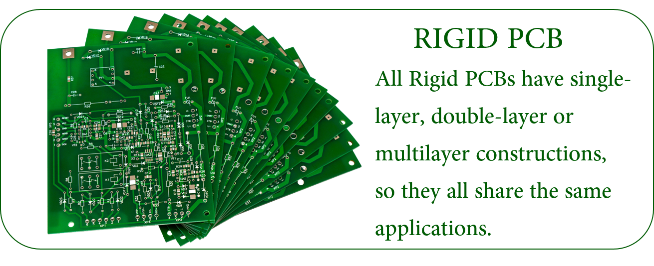
Rigid PCB is a kind of printed circuit board, and is the largest number of PCB manufactured. It is made of solid substrate material, which can effectively prevent the distortion of the circuit board. Perhaps the most common rigid circuit board is the computer motherboard. The motherboard is a multi-layer PCB designed to distribute power from the power supply while allowing communication between all components of the computer, such as CPU, GPU and RAM.
Multilayer Rigid PCB Stackup
Learn more about JHYPCB by exploring the manufacturing capability of Rigid Printed Circuit Board below. We can do more than you can imagine.
Item
Manufacturing Capability
PCB Layers
1-26L (TG135 TG150 TG170 TG180)
Laminate
FR-4, FR- 406, 370 HR ,IT180A,CEM-1, CEM-3,FR1,FR2,94HB,PTFE,etc.
Brand of Laminate
Kingboard,Shengyi,Nanya,Isola,Rogers,etc.
Max Board Size
1-2layers: 1000mm * 600mm
Multilayer PCB: 600* 600mm
Board Thickness
0.1-4.0 mm
Board Thickness Tolerance
±10%
Copper Thickness
1-10 oz
Min Mechanical Drilling Hole Size
4mil(0.10mm)
Min Laser Drilling Hole Size
3mil(0.075mm
Min Line Width/Line Space
2/2mil
Surface Finishes
OSP, HASL, HASL Lead-Free (HASL LF), Immersion Gold(ENIG), Immersion Silver, Immersion Tin, Plated Gold, etc.
Solder Mask Colors
Green, Red, White, Black, Blue, Yellow, Orange, Purple, Gray.
Silkscreen Colors
Black, White, Yellow.
Electrical Testing
Fixture and Flying Probe
Other Testing
AOI, X-Ray(AU&NI), Two-dimension Measurement, Hole Copper Instrument, Impedance Test, Metalloscope, Peeling Strength Tester, Solderability Test, Logic Contamination Test
Special Capabilities
Thick Copper, Thick Gold(60μ"), Gold Finger, Blind and Buried Hole, Countersink Hole, Semi-hole, Peelable Mask, Carbon Ink, Impedance control+/- 10%, etc.
Additional information Rigid PCB,Fr4 PCB,Rigid Circuit Board,Rigid Printed Circuit Board JingHongYi PCB (HK) Co., Limited , https://www.pcbjhy.com
Rigid PCB, the largest number of PCB manufactured
What is Rigid PCB - Rigid PCB Definition
Rigid PCB can be used in any position where the PCB itself needs to be set to a shape and maintained during the remaining life of the equipment. Rigid PCBs can be anything from simple single-layer PCBs to eight or ten-layer multi-layer PCBs.
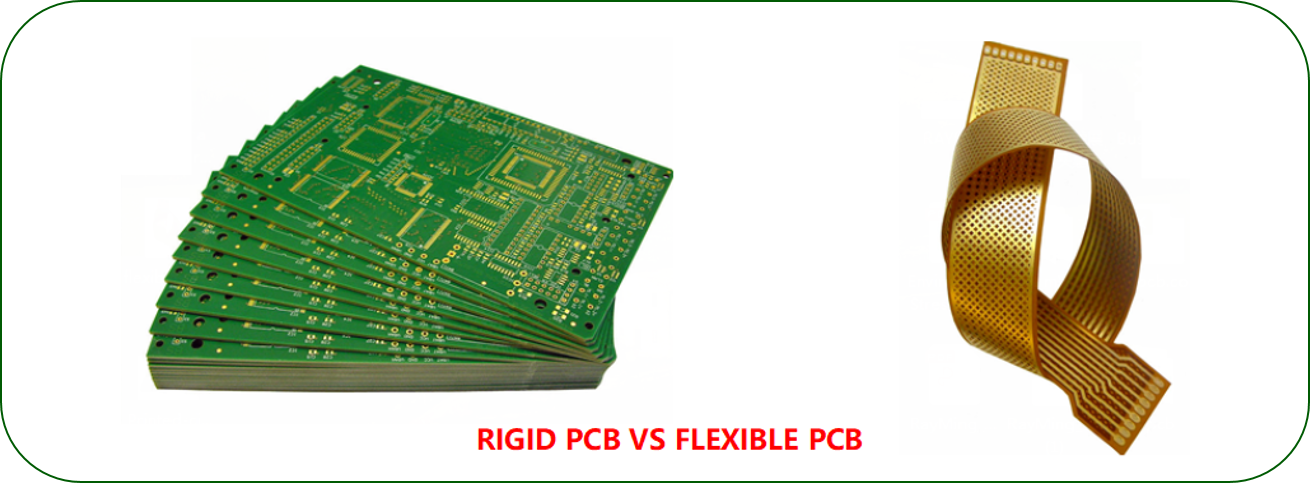
Rigid PCB and Flexible PCB are totally different. One is flexible and the other is rigid. Therefore, their application scenarios are different. In addition, there are rigid-flex PCB. There are similarities between them. However, all rigid PCB have single-layer, double-layer or multi-layer structure, so they have common application scope. This is the case.

Some characteristics of rigid PCB
Rigid PCB manufacturing
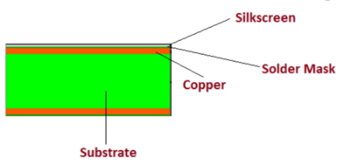
Rigid PCB is made up of different layers that are joined together using adhesive and heat, providing a solid shape to board material. Following layers are used to develop a rigid PCB.
Substrate Layer - rigid PCB material


Copper Layer
Solder Mask Layer
Silkscreen Layer

The differences between Rigid PCB And Flexible PCB
When to Use Rigid and When to Use Flexible
Rigid PCB Applications
Rigid Printed Circuit Board Manufacturer: Guaranteed Quick Delivery
JHYPCB is committed to providing the highest quality rigid printed circuit boards at competitive prices. As the name suggests, these PCBs use an inflexible, solid, and rigid substrate material such as fiberglass, which prohibits these boards from bending. We can provide high-quality, and performance-oriented rigid printed circuit boards in diverse specifications.
Different Types of Rigid PCB Provided by JHY PCB
Matt: Green, Blue, Black.