In Moldex3D R11, we provide some new features including the skin thickness distribution result and overflow setting.
Skin thickness distribution
This is the result showing the actual product residual wall thickness distribution. Below shows  the skin thickness result.
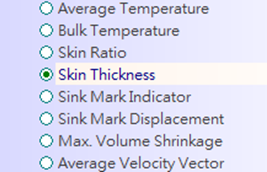
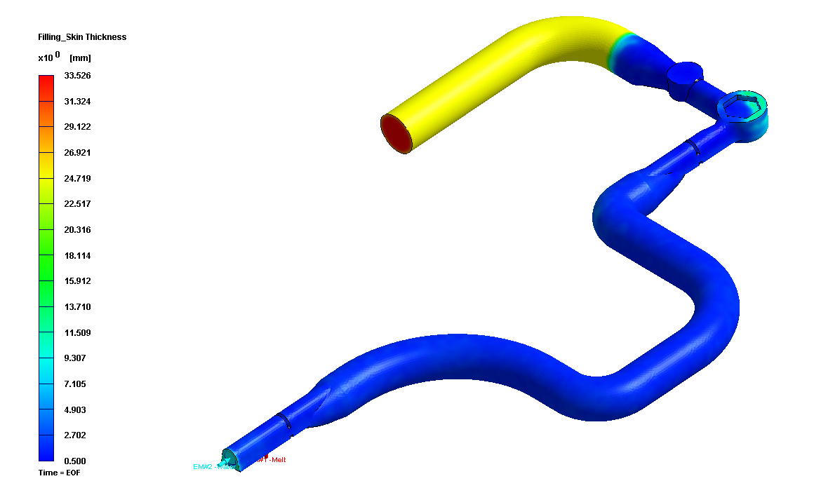 
Skin Thickness Icon
|
Overflow region setting
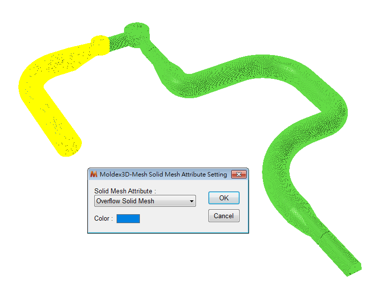
In Moldex3D R11, it supports overflow settings in Moldex3D Mesh. Here are the procedures of the setting:
1. Create an overflow region solid mesh and assign its attribute as “Overflow Solid Mesh.â€
 Â Â Â Â Â Â 
|
2. Export Solid Model
 Â Â Â Â Â Â 
|
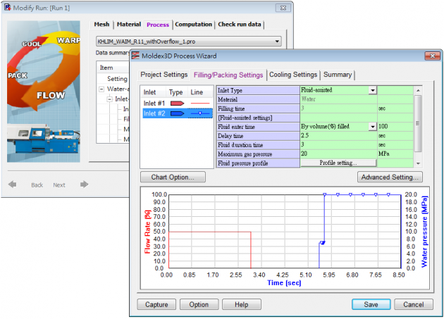
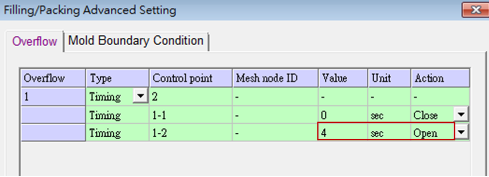
3. Import the model in Moldex3D project and open the Filling/Packing settings subpage. Under “Advanced Settingâ€, we can set the overflow open time. For example, in Figure 5, overflow valve was open at the time of 4 seconds.
 Â Â Â Â Â Â 
|
 Â Â Â Â Â Â 
Fig. Â 5Â Overflow time setting in Moldex3D project
|
Machine Interface
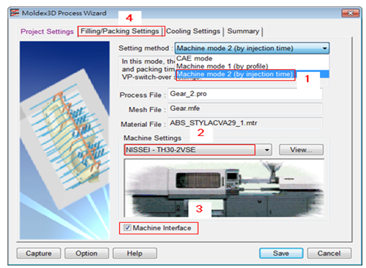
There are four simple steps to activate the machine interface in Moldex3D (Figure 6):
1. Select machine mode 2 at the “Project Setting†tab.
2. Choose an arbitrary NISSEI Machine from the machine database.
3. Click “Machine Interfaceâ€.
4. Go to Filling/Packing Settings page, launch machine interface.
 Â Â Â Â Â Â 
Fig. Â 6 Machine interface setting steps
|
After the interface window was opened (Figure 7), all the settings are exactly the same with the real machine. It’s then very straightforward to covert process conditions in Moldex3D and real world back and forth.
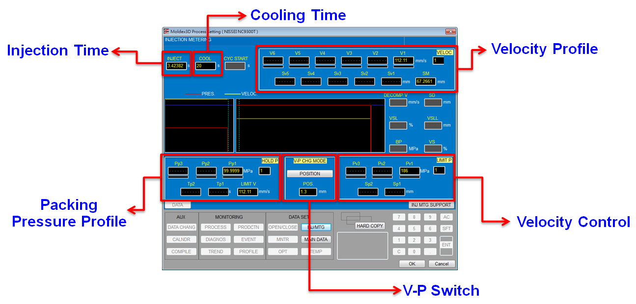 
Fig. Â 7 NISSEI machine interface in Moldex3D R11
|
Hydroxyethyl Cellulose
HEC has many different applications, it can provide good dispersion and stability to various substrates in the coating.
HEC, Hydroxyethyl Cellulose for paint, HEC as thickner in painting
Santo Chemical Limited , https://www.santchem.com


![]()
 Â Â Â
   ![]()
 Â Â Â
   ![]()
 Â Â Â
   ![]()
 Â Â Â
   ![]()
 Â Â Â
   ![]()

![]()